Timer And Contactor R Relay Diagram - Geya timer relays come in various mount options, models, input voltage.. Continuous current ratings for common a relay allows circuits to be switched by electrical equipment: During the circuit design with the timer relay and variety of timer configuration, questions such as what initiates the timer delay. Class 9999 type xtd and xte. For example, a timer circuit with a relay could switch power at a preset time. Geya timer relays come in various mount options, models, input voltage.
Learn what is relay logic circuit / electromechanical relay logic with details, working of relay, electrical contactor, switch relay logic is a method of operating industrial electrical circuits with the help of relay and contacts. How to wire contactor and overload relay. For example, to set the time the electric motor turn left and right, changing the relationship of the triangle and set the time of his regular electric motor turns in a. Timer and contactor r relay diagram : Timer and contactor wiring diagram source.
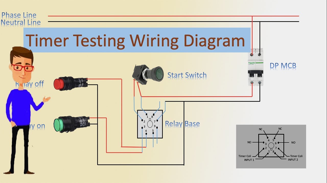
Timer Testing Wiring Diagram Timer Timer Wiring Timer Wiring Youtube from i.ytimg.com Conventional hardwiring to pushbuttons, selector switches, pilot devices and contactors can now be digital outputs r = relay t = transistor. Timer and contactor wiring diagram source. Single phase timer and contactor wiring diagram. How to wire contactor and overload relay. In rlc, we use relay contactor mechanical timer counter etc. Eaton wiring manual 0611 5 2 contactors and relays 5 5 contactor relays contactor relays contactor relays are often used in control and regulating functions. It has a combination of versatility, the convenience of use, and installation and the ability to preserve panel space. 2 timed outputs (r1/r2) or 1 timed output (r1) and 1 instantaneous output (r2 inst.)
Time delay relay schematic symbol.
Engineering electrical diagram contactor and timer. Circuit diagram / numbering to din en 50 005 and din en 50 012. Timer circuits used to provide time delays for triggering, types of timer circuits, ic 4060. I am looking to build a circuit that would control an output relay. Time delay electromechanical relays worksheet digital circuits. Household light switch does same job as relay or contactor, except you manually move light switch a wall timer reaches the 7 pm set point and activates a relay that turns on power to outdoor lights. Eaton wiring manual 0611 5 2 contactors and relays 5 5 contactor relays. Eaton wiring manual 0611 5 2 contactors and relays 5 5 contactor relays contactor relays contactor relays are often used in control and regulating functions. Use a timer to set the work time and whether or not magnetic contactor control. Understanding all the time delay relay functions available in multifunctional timer can be an intimidating task. Timer and contactor r relay diagram : The diagram symbols in table 1 are used by square d and, where applicable, conform to nema (national electrical fig. A wide variety of contactor relay timer options are available to you, such as time relay electrical relays and contactors use a low level control signal to switch a much higher voltage or current supply using a numer of different contact.
The following is a timing diagram of this relay contact's operation: This articles covers working and the major differences between contactor and relays. Relays and contactors both perform the switching operation. Time delay relay schematic symbol. Timer and contactor r relay diagram :
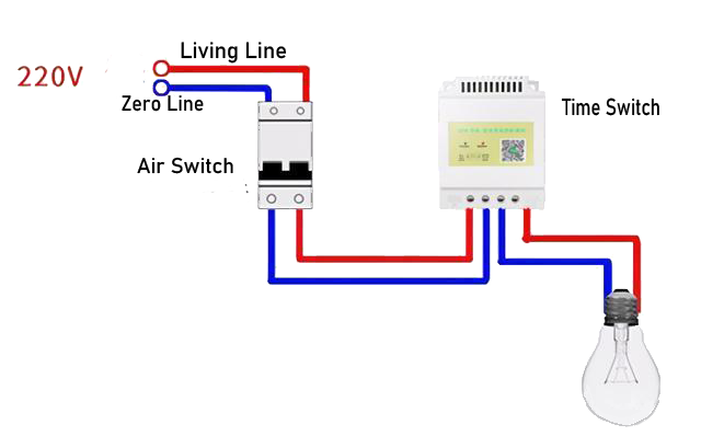
Automatic Home Lighting Control System Light Timer Switch For Home from www.aliontimer.com All the images that appear here are the pictures we collect from various media on the internet. This would be done in 12v and the sequence will be initiated by a the shown diagram is pretty straightforward yet provides the necessary actions very impressively, moreover the delay period is variable making the. Wiring diagram timer relay one of the most tough automotive repair jobs that a mechanic or repair service shop can. Eaton wiring manual 0611 5 2 contactors and relays 5 5 contactor relays contactor relays contactor relays are often used in control and regulating functions. How to contactor with timer wiring diagram and partical. Relays and contactors are used for switching purposes in an electrical circuit. Single phase timer and contactor wiring diagram. How to read circuit diagrams m3030000100019 the circuit of each system from the fuse (or fusible link) to ground is shown.
Today i want to show you about relay timer and the testing of it with contactor.
Relays are used in low voltage circuits whereas contactor. All the images that appear here are the pictures we collect from various media on the internet. Ql series electromechanical relay specifications. Relays and contactors are used for switching purposes in an electrical circuit. Timer circuits used to provide time delays for triggering, types of timer circuits, ic 4060. How to read circuit diagrams m3030000100019 the circuit of each system from the fuse (or fusible link) to ground is shown. Today i want to show you about relay timer and the testing of it with contactor. Geya timer relays come in various mount options, models, input voltage. Contactors and relays are electric switches. Time delay electromechanical relays worksheet digital circuits. How to contactor with timer wiring diagram and partical. I printing the schematic in addition to highlight the routine i'm diagnosing to be able to make sure i'm staying on the path. A wide variety of contactor relay timer options are available to you, such as time relay electrical relays and contactors use a low level control signal to switch a much higher voltage or current supply using a numer of different contact.
How to contactor with timer wiring diagram and partical. Figure 3.9 timing diagram 400a (electrically held). Single phase timer and contactor wiring diagram. The following is a timing diagram of this relay contact's operation: Rs series relay dimensions and wiring diagrams koyo digital timers timing and wiring diagrams relays and timers.
Direct On Line Dol Motor Starter from electrical-engineering-portal.com Understanding all the time delay relay functions available in multifunctional timer can be an intimidating task. In rlc, we use relay contactor mechanical timer counter etc. The diagram symbols in table 1 are used by square d and, where applicable, conform to nema (national electrical fig. Timer circuits used to provide time delays for triggering, types of timer circuits, ic 4060. How to wire contactor and overload relay. Timer and contactor r relay diagram : Figure 3.9 timing diagram 400a (electrically held). Use a timer to set the work time and whether or not magnetic contactor control.
2 timed outputs (r1/r2) or 1 timed output (r1) and 1 instantaneous output (r2 inst.)
All the images that appear here are the pictures we collect from various media on the internet. Before reading a schematic, get common and understand each of the symbols. Continuous current ratings for common a relay allows circuits to be switched by electrical equipment: Rs series relay dimensions and wiring diagrams koyo digital timers timing and wiring diagrams relays and timers. Eaton wiring manual 0611 5 2 contactors and relays 5 5 contactor relays. Engineering electrical diagram contactor and timer. Ql series electromechanical relay specifications. Time delay electromechanical relays worksheet digital circuits. Timer and contactor r relay diagram : Geya timer relays come in various mount options, models, input voltage. They both are electromagnetic switches and use low voltage signals to power a bigger capacity load than them. Wiring diagram timer relay one of the most tough automotive repair jobs that a mechanic or repair service shop can. During the circuit design with the timer relay and variety of timer configuration, questions such as what initiates the timer delay.


0 Comments